Automatic leveling for the Anycubic i3 Mega
MenuI love that printer but one of the features that is sorely missing on it since the Ultrabase version is automatic levelling! Not only is this function damn useful, it also compensates for small level differences that are not necessarily visible to the naked eye. These compensations allow you to improve the adhesion of your prints to the bed.
Warning: this tutorial requires some welding knowledge and some electronic equipment. But it's well worth it! In this article, I will describe how you can install a BLTouch on your Anycubic i3 Mega.
Shopping list
- The probe (clone of BLtouch) : ~14$ (you will probably find some cheaper ones but I can't guarantee that they are of good quality...)
- Male to female Dupont cables of at least 30cm: ~$1.49 (if you have a cable crimping tool, the best thing to do is to make these cables yourself, but it's not common...)
- 2.54mm connectors: ~$1.22 (you will probably have enough for a lifetime, that's the magic of Aliexpress...)
- 4 loose nuts M3 and 4 bolts M3x12
- A soldering iron and tin
In addition to this, you will need to print a holder for the probe: https://www.thingiverse.com/thing:2824005 (credits to Petrzmax)
You're ready to start!
Probe installation
Installing the sensor socket
A plug must be added to the small electronic circuit in the print head carriage. This circuit will allow the probe signal to be sent to the already wired circuits of the mainboard without requiring too many modifications.
Use two 2.54mm connectors for this purpose.
Be careful when soldering the plug not to overflow onto other connectors and check more than once that you are installing it in the right place.

(Crédits à Euk_rob pour la photo)
Mounting the BLTouch on the x carriage
To attach the sensor to the trolley, we need a small adapter. I printed it using a DLP (Anycubic Photon) printer, but you can do it with a conventional FDM printer, preferably using a high temperature resistant material (PETG or ABS).
The piece is on Thingiverse: https://www.thingiverse.com/thing:2824005 (credits to Petrzmax)
You will need the 4 M3 nuts and 4 M3x12 bolts to attach it to the trolley's ventilation grid.
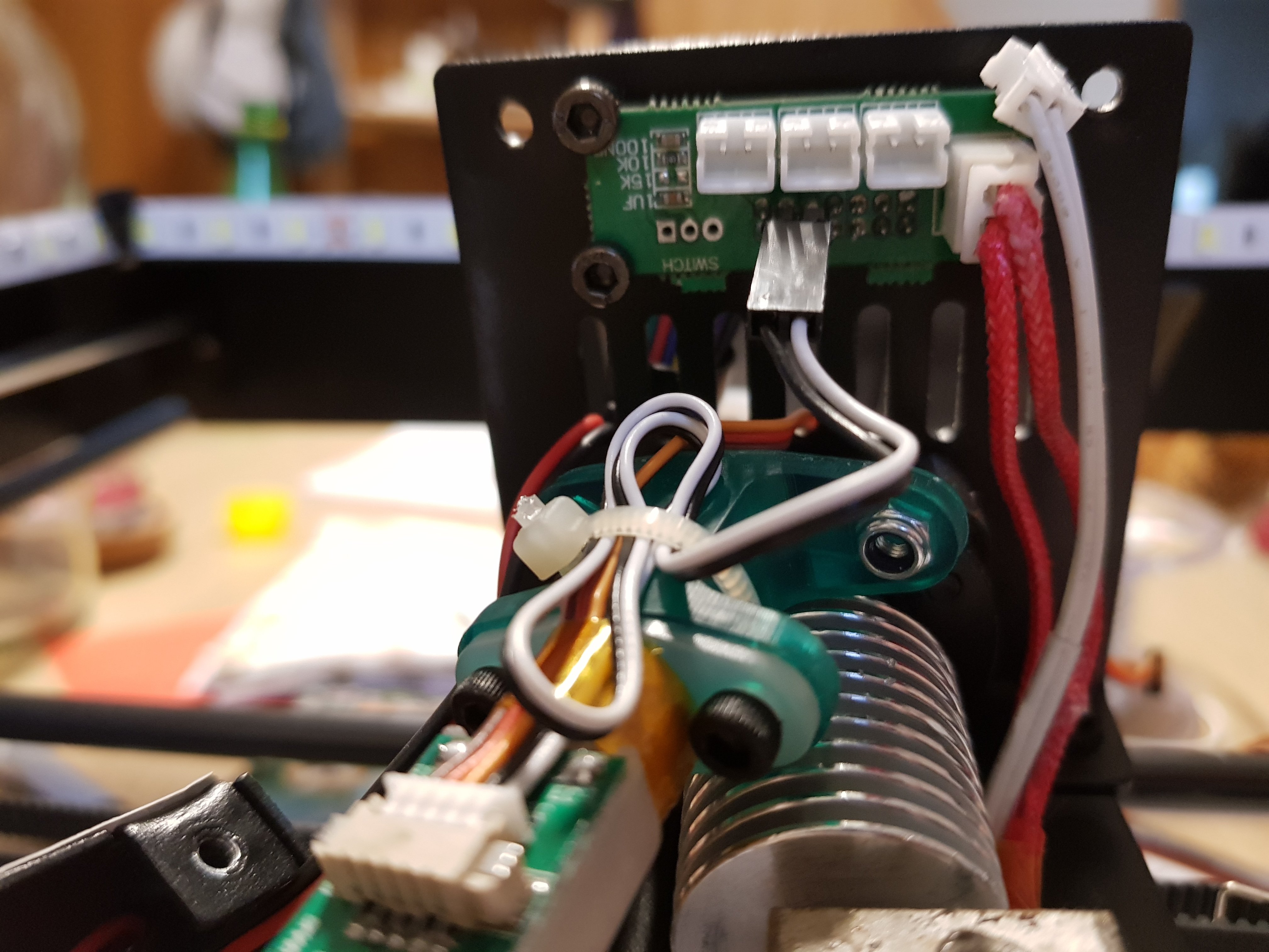
Connect the black and white cable to the newly soldered plug, as shown in the picture above.
Then, pass the tricolor plug through one of the fixing holes to remove it from the carriage.
Place the cables neatly by attaching them with zips and replace the cover. This is a delicate step because you must make sure that your cables are not in contact with the hotend and that they are not in front of a fan, which would hinder the air flow.
Once this is done, make a plug with 3 thin cables and male Dupont plugs:
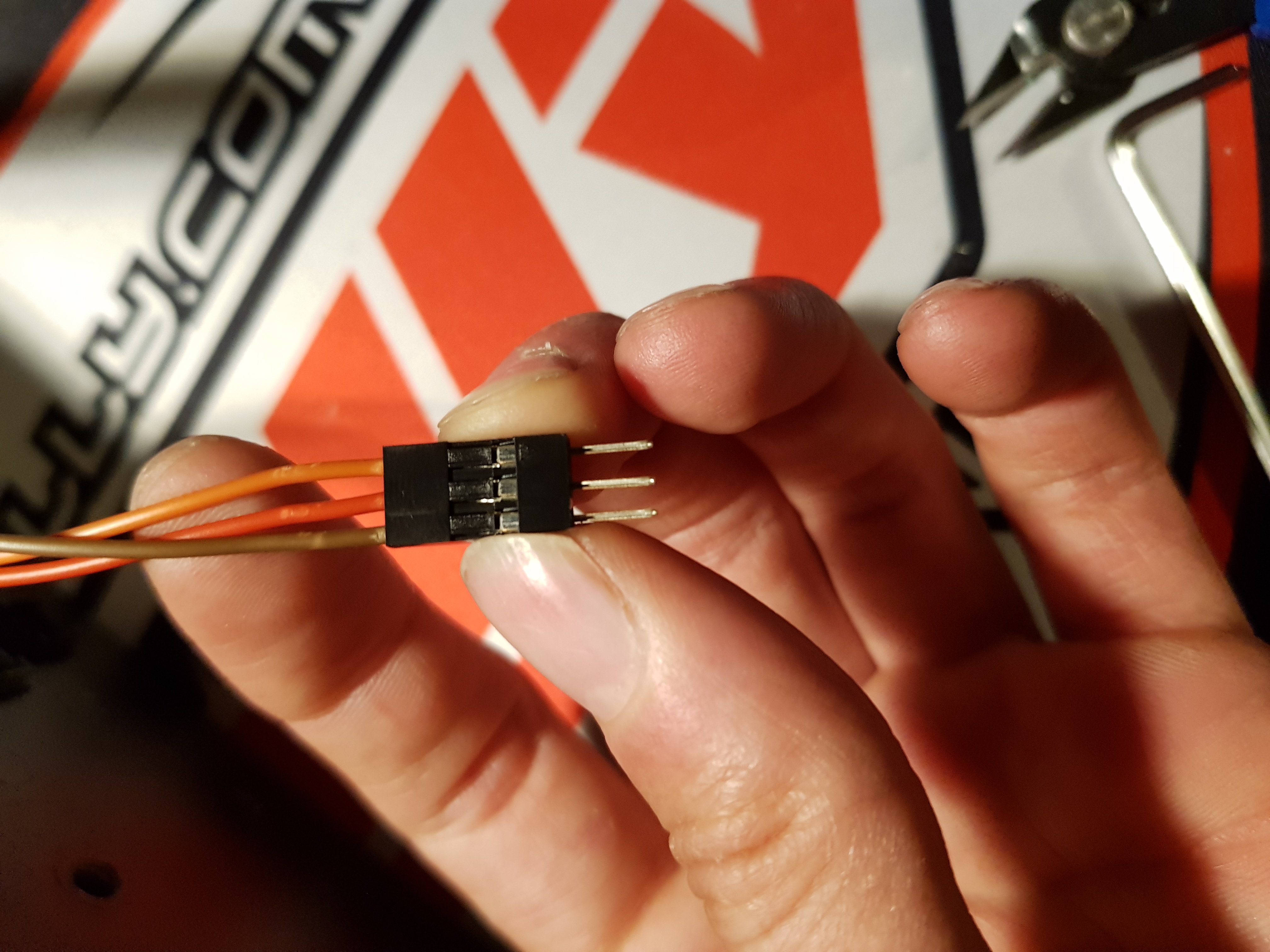
This plug will connect the sensor of the X carriage with the mainboard.
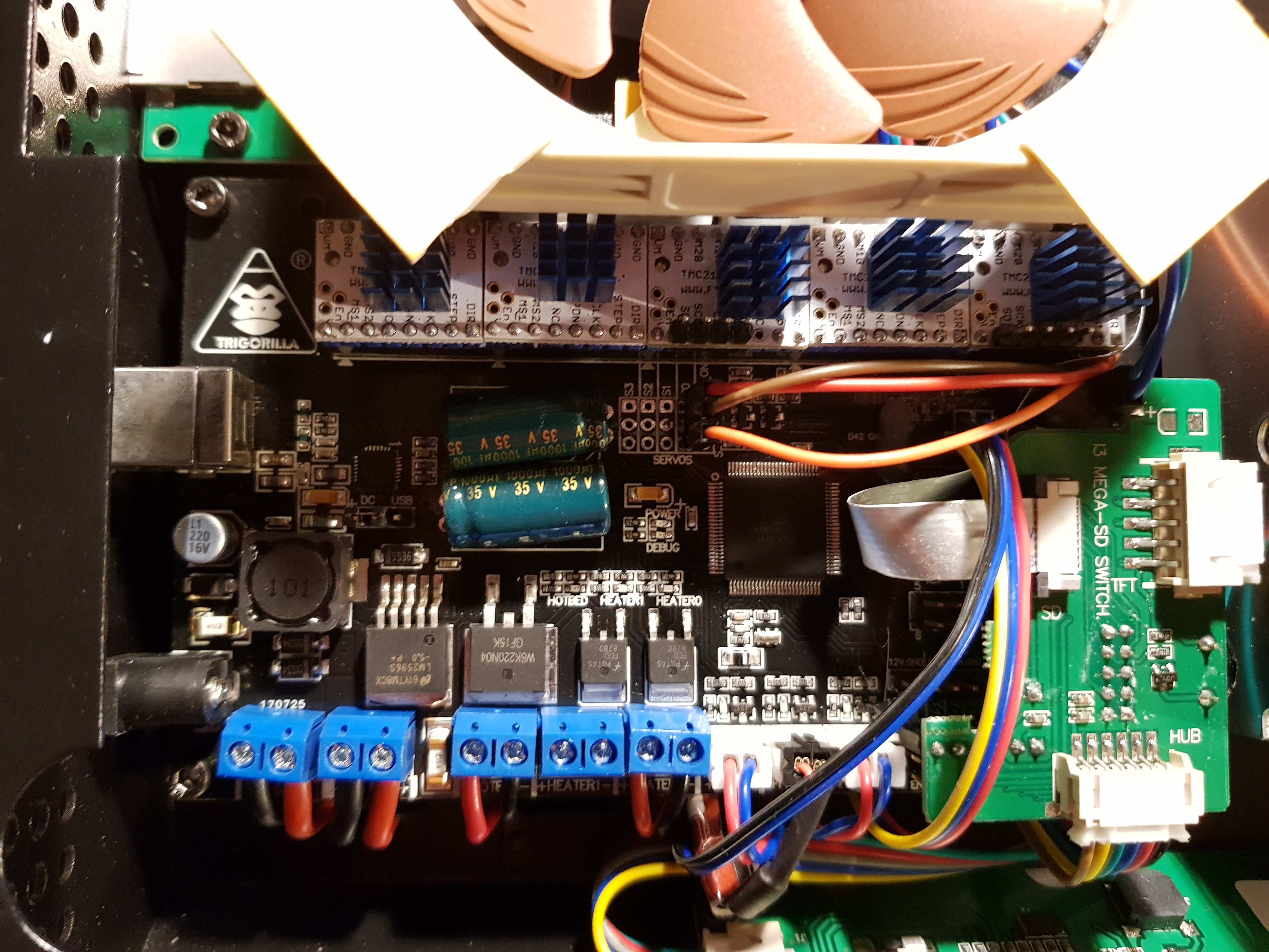
Crimp the other side with female plugs to connect them on the mainboard to the S0 location like this (the red, brown and orange plug):
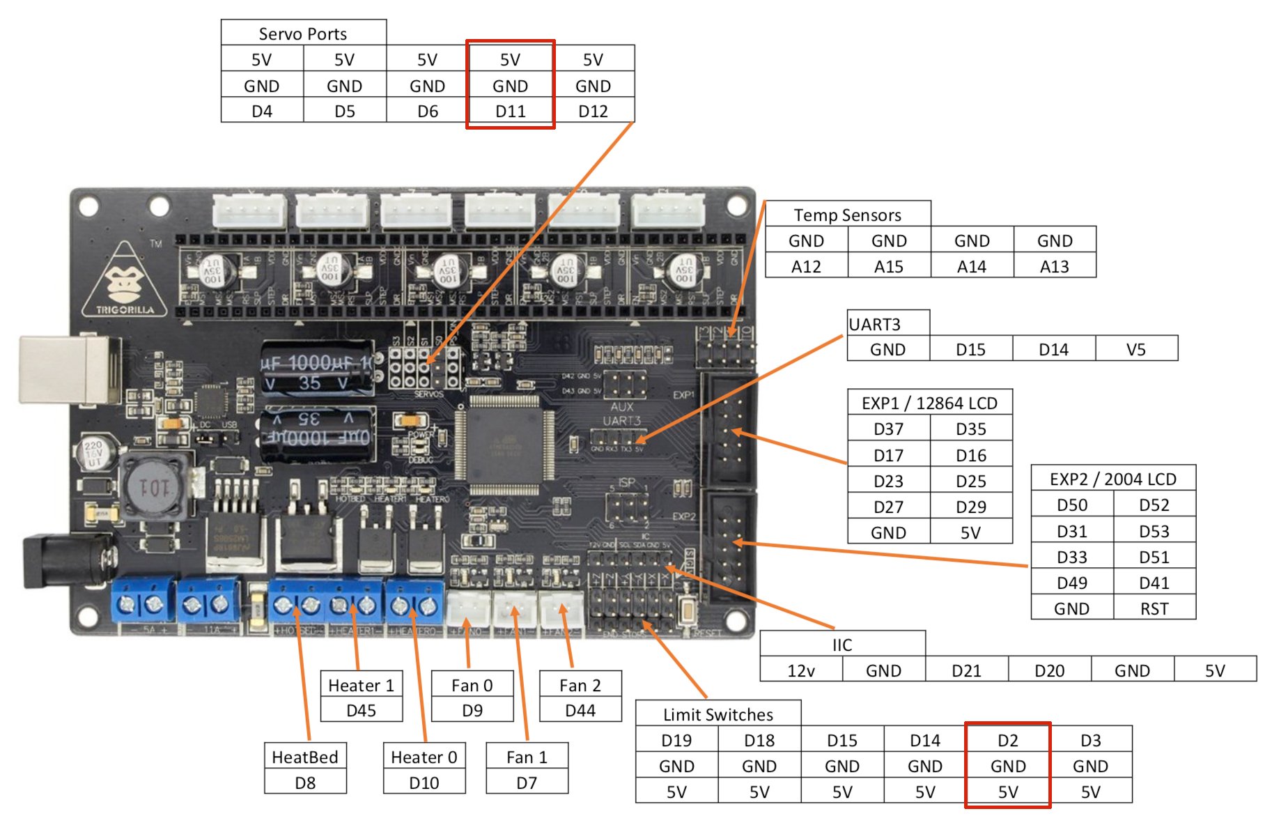
Installation diagram :
Firmware update
Now that the hardware is installed, the software must be updated to support the probe.
Warning: this operation will cause you to lose the resumption of printing in the event of a power failure.
The firmware I wanted to offer you was based on the work of Systemik, published on Github at the following address: https://github.com/systemik/Marlin/
However, I had some concerns that prevent me from publishing it for the moment, so I will share with you the link to a firmware based on the work of Euk_rob from Thingiverse. Download the firmware at the following address: https://www.dropbox.com/sh/
In addition to adding level sensor management, fixing countless small bugs, it removes the i3 Mega's startup sound (no one will miss it) and makes some slight improvements in print quality.
Start by downloading this new firmware here:
Then connect your USB printer to your PC using the cable provided by Anycubic. Install the printer driver if it is not already installed (the driver is provided on the SD card sold with the printer).
Then open Cura and click on "Settings > Printer > Manage printers", select your printer from the list and click on "Upgrade firmware".
Look for the firmware downloaded above and validate.
Wait until everything is finished (may take 1 or 2 minutes). Then turn off the printer and turn it back on again.
When you turn it on, you should hear the probe start (3-4 clicks). You are now ready to test a print!
Level adjustment and Cura preparation
Do the first time the level of your tray as you usually do. It will serve as a basis for our work.
In the firmware, it is indicated that the probe is located 1mm below the nozzle. You can adjust this setting according to your observations.
In Cura, go to "Settings > Printer > Manage printers", select your printer and click on Machine Settings. In the "Start G-code" section, add the following lines (those in bold):
G21 ;metric values
G90 ;absolute positioning
G28; Home axis
M851 Z-0.65;
G29; Enable Auto Bed Levelling (ABL)
M500; Save firmware
M420 S1; Enable BLTouch
M82 ;set extruder to absolute mode
M107 ;start with the fan off
G28 ; Home the axis I hope
G1 Z15.0 F3600 ;move the head up 15
G92 E0 ;zero the extruded length
G1 F200 E3 ;extrude 3mm
G92 E0 ;zero the extruded length again
G1 F3600
The red line is used to adjust the position of the nozzle in relation to the plate. Adjust it as follows:
Above 0, the nozzle is top close to the plate, you want to move it away (example: 0.4mm is further away than 0.2mm)
Below 0, the nozzle is too far from the plate and you want to bring it closer (example: -0.7mm is closer than -0.5mm)
To start testing, I advise you to put -0.6, see if the first layer is too high, if so, lower as you go. It may take some time to adjust but once you find the right setting, you won't have to change it anymore:)
Finally, launch a first impression of a freshly cut object in Cura, you should find the same behavior at the beginning of printing as in the following video:
Problem!
Everything seemed to be going well until I wanted to start printing in max quality (0.1mm thick layers)... The filament started melting far too early in the hotend and ended up butchering it!
The space is running out in the X-axis cart, you'll have to open it so that it can get airy! Finally, we're going to have to find a way out.
Fortunately the makers community is there and has already thought of everything!
The following parts are to be printed in a heat-resistant material, I made it in PETG, you can make it in ABS too or even better: in resin if you have the required material.
https://www.thingiverse.com/thing:2428939
On the source, several versions are available, I took the first version where the side openings are cut, the latest version has a grid to avoid putting his fingers on the fan. It's up to you to see which version you prefer.
You will also need 4 M3x12 bolts and 4 M3 nuts.
Then remove the printer cover and replace it with the freshly printed elements:
Now the air can circulate freely in the print head again! Ideally, the wiring should also be simplified by replacing the Noctua connectors with soldering, but this will be for another time!
Conclusion
This new accessory allows the printer to compensate for flatness defects in the tray. In the end, it allows you to miss your impressions less often and to obtain better results for the first layers.
Changing the firmware is essential and allows you to continue to improve some of the printer's settings or functions. Further improvements are in preparation and will follow ;-) Thanks to Anycubic for sharing the source code of the i3 Mega. Thanks to all the hackers including Petrzmax and Euk_rob for their guides from which I got inspired and to all the others anonymous or not for adapting Marlin and adding the basic functions of the i3 Mega on it!
Site web créé avec l'aide de Wikeo